Heat Sink Calculator Excel

Sizing Heat Sinks Using A Few Simple Equations Heat Sink Calculator Blog Focused On Heat Sink Analysis Design And Optimization

Heat Sink Design Calculators Thermal Analysis Software

Xl4sim Excel Finned Heat Sink Analysis Add In

Download Hvac Duct Measurement Excel Sheet Xls Hvac Duct Hvac Duct

Online Heat Sink Analysis And Design Heatsink Design Power Source

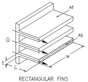
Flat Plate John R Wilson S Blog

The heat sink size calculator is based on a well established equation for estimating heat sink volume during the early stages of heat sink design.
Heat sink calculator excel.
Heat Sink Convection With Fins Calculator Engineers Edge Www Engineersedge Com
The User Interface Of The Luminaire Design Calculator Excel Spreadsheet Download Scientific Diagram

Download Free Psychrometric Excel Calculator Xls Psychrometric Chart Excel Calculator

Heat Sink Size Calculator
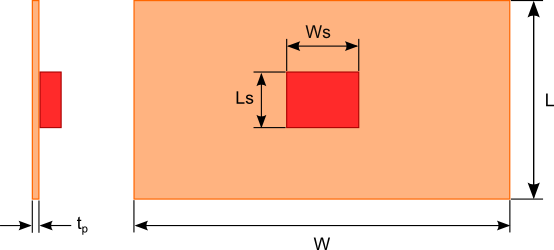
How To Design A Flat Plate Heat Sink Heat Sink Calculator Blog Focused On Heat Sink Analysis Design And Optimization

Pin On Hvac
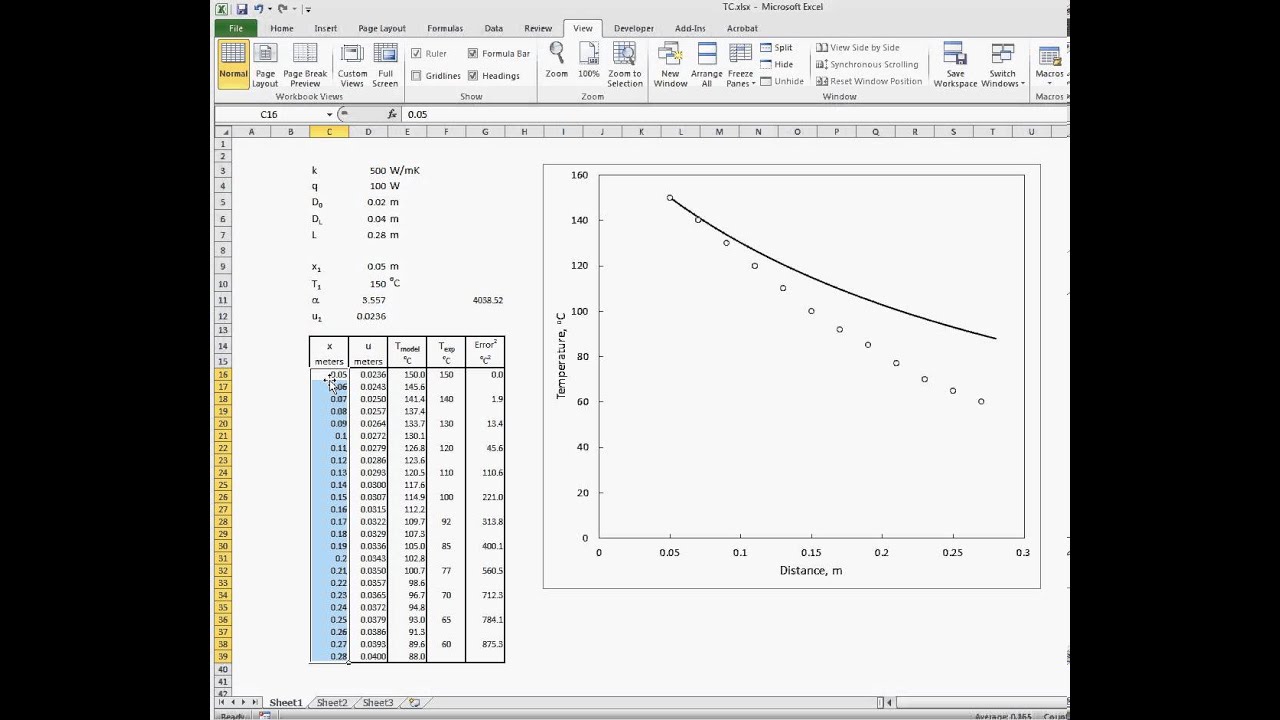
Thermal Conductivity Excel Calculations Youtube
Advanced Plate Fin Heat Sink Calculator Myheatsinks

Pin On Hvac

Download All Smoke And Ventilation Calculation Excel Sheets Transformer Room Ventilation Generator Room Ventilation Lt Ht Room Ventilation Ventilation Smoke
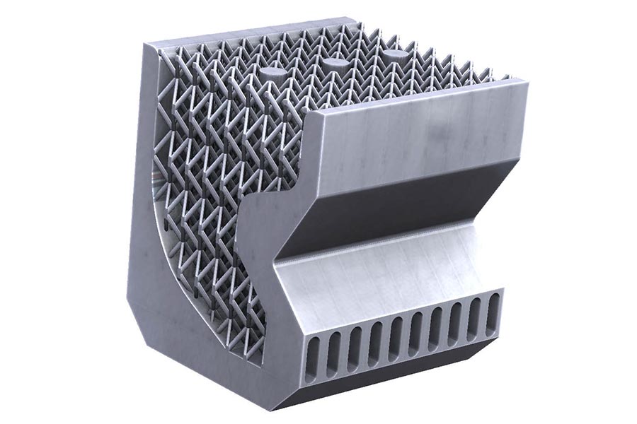
Building The Ideal Heat Sink Mechanical Engineering Purdue University

Pin On Hvac

Rainwater Drainage Design Calculation Excel Sheets Xls Rainwater Drainage Drainage Rainwater
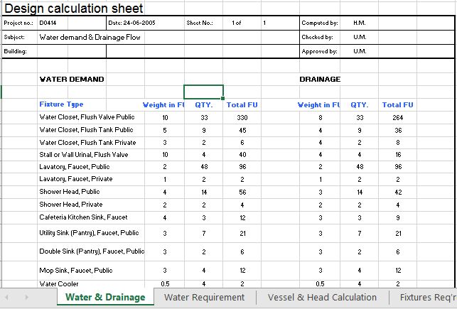
Water Demand Calculations Excel Sheet Xls Calculator

Download Duct Cost Estimator Spreadsheet Xls For Free Clean Air Ducts Hvac Duct Hvac Filters

Pin On Hvac

Https Encrypted Tbn0 Gstatic Com Images Q Tbn 3aand9gcrdkyrhd U5clfep Ipgj72e Bzabrslw 02w Usqp Cau

Kpi Dashboard Developed In Excel On Chandoo Org For Smaller Data Management Projects Excel Dashboard Templates Kpi Dashboard Excel Tutorials
Https Encrypted Tbn0 Gstatic Com Images Q Tbn 3aand9gcsyofd U8uhkniprgjwpbbavboyqjk3ygschqacikek9is162t7 Usqp Cau
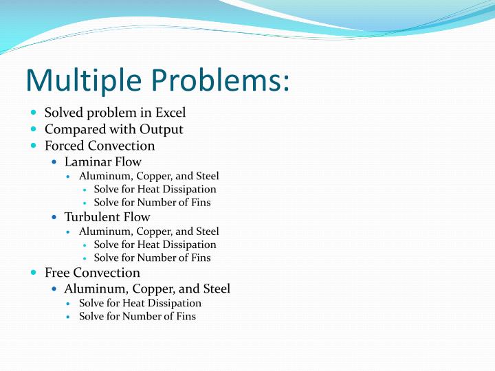
Ppt Heat Sink Calculator Powerpoint Presentation Free Download Id 269840

Download A Free Calculation Excel Sheet For Pump Head Calculations For Chilled Water Systems Of Central Air Con Water Pump System Water Systems Heating Systems

Management Excel Project Management Free Templates Resources Guides Informa Project Management Dashboard Project Management Free Excel Dashboard Templates

Solving The Two Dimensional Heat Conduction Equation With Microsoft Excel Solver Youtube
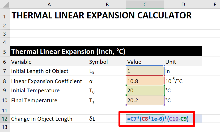
How To Calculate Linear Thermal Expansion For Measurement Uncertainty
Source : pinterest.com
